| English | Japanese |
|
Yesterdays access |
|
| Page Top | [Lily Diary.】 A diary of life in Mindanao. |
| 26/11/07 | SatBox_Ver0.1.1c-beta IC-9700 Test Version |
| 26/11/07 | SatBox User Guide |
| 26/11/03 | An FT-847 for SatBox Development |
| 26/11/02 | Buying a ZT219 Digital Multimeter |
| 26/10/28 | Building a home server using Linux |
| 26/10/27 | Repeater Controller Features and Settings |
| 26/10/27 | Repeater Controller Board and Firmware |
| 26/10/26 | JTDX Auto Run Ver0.7.7 |
| 26/10/26 | WSJT-X Auto Run Ver0.1.6 |
| 26/10/22 | Memories of UNIX and Networking from My Yonezawa Ham Shack |
| 26/10/20 | Acquiring a YAESU FT-2600M for a Repeater |
| 26/10/19 | Rotator Relay Interface for Sale |
| 26/10/18 | Kenpro Rotator Interface KiCAD DATA |
| 26/10/17 | JOTA in Indonesia: Jamboree on the Air |
| 26/10/17 | You Can Now Leave Comments |
| 26/10/11 | Installing Arduino IDE |
| 26/10/09 | DXCC200 Sticker Arrives from ARRL |
| 26/10/08 | SatBox Cloud Released |
| 26/10/06 | Bought an ECS LIVA Z Mini PC on Yahoo Auctions |
| 26/10/05 | QSO with C5R in The Gambia |
| 26/10/04 | Installing Raspberry Pi OS |
| 26/10/02 | Repeater Controller Features and Settings |
| 26/10/01 | Repeater Controller Board and Firmware |
| 26/09/30 | Ordering PCBs and Assembly from JLCPCB |
| 26/09/24 | UNITRUST Electronics Parts Shop |
| 26/09/22 | Kenpro Rotator Interface |
| 26/09/18 | SatBox KiCad PCB and firmware |
| 26/09/14 | designed a circuit board for SatBox |
| 26/09/12 | Solar Power System Plan |
| 26/09/09 | Satellite SatBox Part 4 |
| 26/09/04 | My grandson Zion |
| 26/08/29 | Ham Fair 2026 to be held |
| 26/08/25 | QSO with RI1FJL from Franz Josef Land |
| 26/08/23 | Satellite QSO via RS-44 |
| 26/08/22 | Currently, Satellite VUCC46 |
| 26/08/16 | Satellite SatBox Development in Progress - Part 3 |
| 26/08/05 | IC-820H Receiver Sensitivity Test |
| 26/08/02 | Satellite SatBox Development in Progress - Part 2 |
| 26/07/16 | Delivery of the 3D printed panels |
| 26/07/09 | Development of SatBox for satellites |
| 26/07/05 | Weather Monitor Indoor Unit |
| 26/06/30 | Creating data for 3D printers using FreeCAD |
| 26/06/16 | Installing an AS5600 magnetic encoder on a KR-500. |
| 26/06/05 | Grandson Zion's CQ |
| 26/06/04 | Replacing the potentiometer on the KR-500 elevation rotator |
| 26/06/03 | Making a Repeater Controller Pert4 |
| 26/06/01 | Weather Monitor software |
| 26/05/31 | Weather Monitor |
| 26/05/21 | JTDX Auto Run BUGFIX |
| 26/05/17 | Repair of satellite antenna system |
| 26/05/13 | Repair of Alinco DR130 |
| 26/05/07 | Making a Repeater Controller Pert3 |
| 26/05/03 | Indonesian satellite friend YC8RPK |
| 26/04/26 | DXCC200 achieved |
| 26/04/23 | Communication via ISS voice repeater |
| 26/04/20 | WSJT-X Auto Run Ver0.1.5 |
| 26/04/19 | Got an Alinco DR-130 |
| 26/04/15 | Clublog Charts |
| 26/04/10 | Regarding POC transceivers |
| 26/04/08 | Using KENWOOD AT-300 with YAESU radio |
| 26/03/17 | How to establish a radio club in the Philippines |
| 26/03/10 | KENWOOD AT-300 with YAESU radio |
| 26/02/27 | Philippine NTC Amateur Radio License Examination Question Bank |
| 26/02/20 | Package received from JK1SNS |
| 26/02/18 | Temporary License Renewal |
| 26/02/14 | Satellite Tracking Software SatTrack |
| 26/02/05 | Making a Repeater Controller Pert2 |
| 26/02/02 | CQ on satellite IO-86 |
| 26/01/27 | Shack & Repeater Controller |
| 26/01/16 | Making a Repeater Controller |
| 26/01/16 | Making aRotator Interface PCB |
| 26/01/10 | Satellite antenna installation |
| 26/01/08 | WSJT-X Remote Operation |
| 26/01/07 | JTDX Remote Operation |
| 26/01/04 | log_reciver_Ver2.6.6 |
| 26/01/04 | Tailscale VPN software for JTDX_Remote |
| Online Multiple Choice Reviewers to the Phil Amateur Radio Examination by 4F3EW A joint project by JI1FGX/DU9 and DV9JRD |
| Repeater Controller Features and Settings (October 2, 2026) | ||||||||||||||||||||||||||||||||||||||||||||||||||||||||||||||||||||||||||||||||||||||||||||||||||||||
|---|---|---|---|---|---|---|---|---|---|---|---|---|---|---|---|---|---|---|---|---|---|---|---|---|---|---|---|---|---|---|---|---|---|---|---|---|---|---|---|---|---|---|---|---|---|---|---|---|---|---|---|---|---|---|---|---|---|---|---|---|---|---|---|---|---|---|---|---|---|---|---|---|---|---|---|---|---|---|---|---|---|---|---|---|---|---|---|---|---|---|---|---|---|---|---|---|---|---|---|---|---|---|
| Repeater Controller Touchscreen Display
Standby (STATE: IDLE) The controller is waiting for an incoming signal. The display shows the current TOT, HANG, CW ID, and other settings. 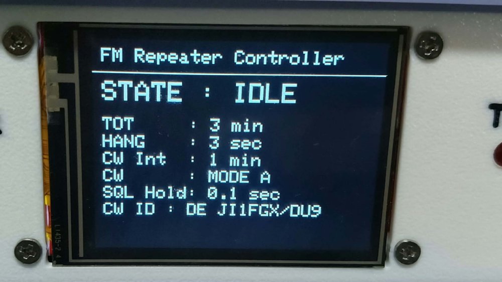 |
||||||||||||||||||||||||||||||||||||||||||||||||||||||||||||||||||||||||||||||||||||||||||||||||||||||
Repeating an Incoming Signal (STATE: TX)An incoming signal has been detected on the receiver (uplink), and the transmitter (downlink) PTT is activated to relay it. 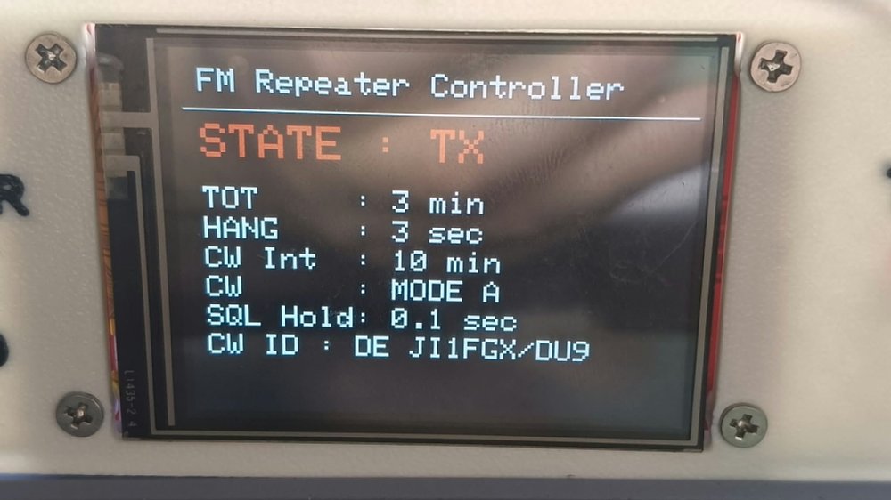 |
||||||||||||||||||||||||||||||||||||||||||||||||||||||||||||||||||||||||||||||||||||||||||||||||||||||
Transmit Hold (STATE: HANG)
Transmission continues for the configured HANG time after the received signal ends. If another signal arrives during this period, normal repeating resumes.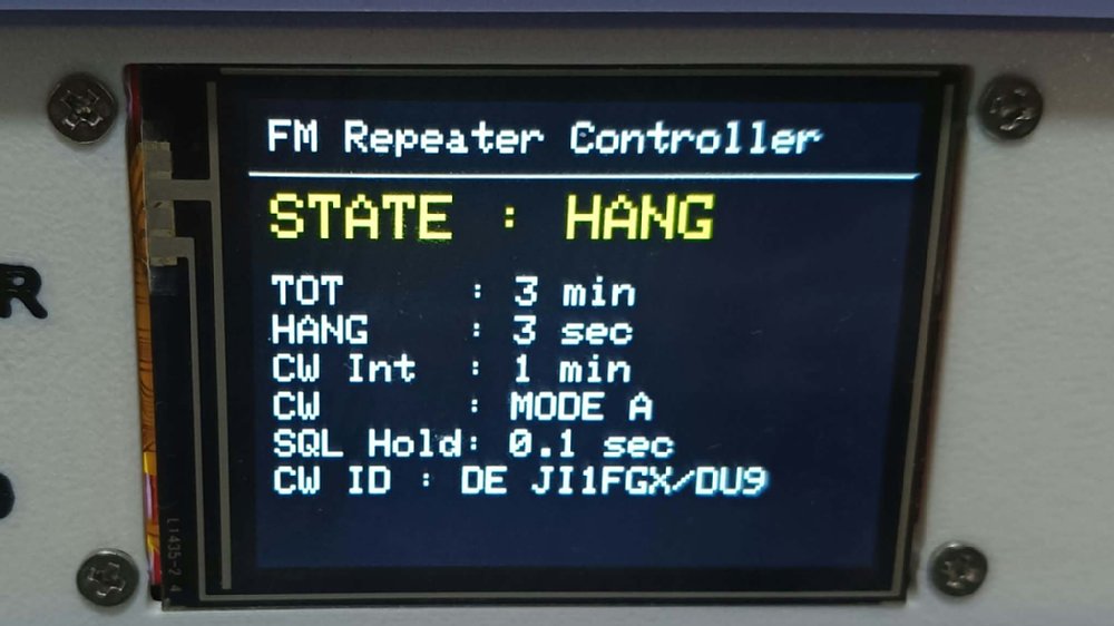 |
||||||||||||||||||||||||||||||||||||||||||||||||||||||||||||||||||||||||||||||||||||||||||||||||||||||
Transmitting a CW IDThe configured message, such as your call sign, is transmitted in Morse code.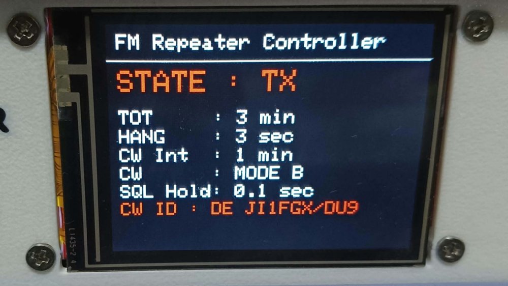 |
||||||||||||||||||||||||||||||||||||||||||||||||||||||||||||||||||||||||||||||||||||||||||||||||||||||
| Transmitting a Voice ID
The DFPlayer plays audio files for the time signal, spoken time, and call sign. Sample audio files are provided. Prepare suitable recordings for your own station. 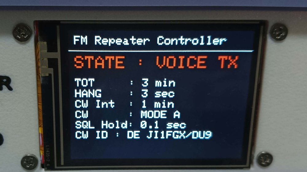 |
||||||||||||||||||||||||||||||||||||||||||||||||||||||||||||||||||||||||||||||||||||||||||||||||||||||
| TOT (Time-Out Timer): Limiting Continuous TransmissionWhen the time limit is reached, transmission stops and the controller enters TOT lockout. The controller returns to standby after the receive input remains inactive for the TOT_LOCK period. 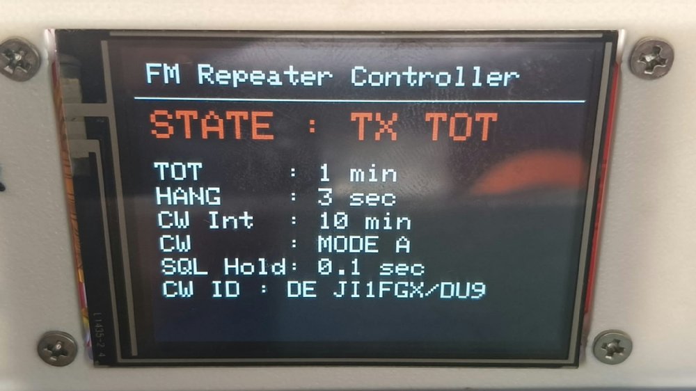 |
||||||||||||||||||||||||||||||||||||||||||||||||||||||||||||||||||||||||||||||||||||||||||||||||||||||
| Settings Screen
Tap an item while the controller is idle to edit it. The selected item turns red. Use [-] and [+] to change the value, then tap [OK] to save. Repeater operation is suspended while editing settings on the touchscreen. TOT: Continuous transmission limit, adjustable from 1 to 30 minutes. 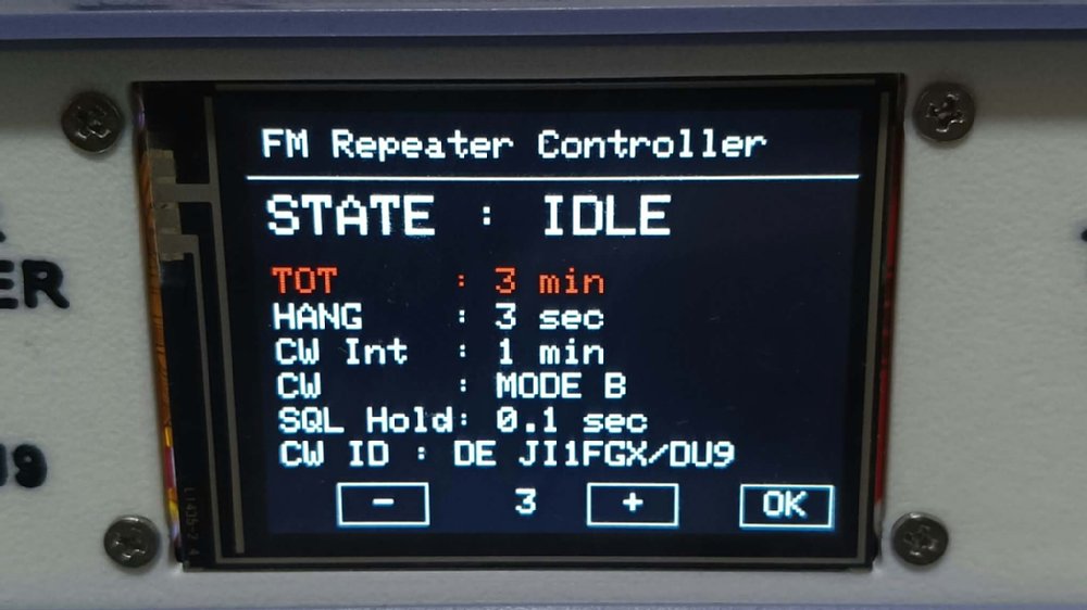 |
||||||||||||||||||||||||||||||||||||||||||||||||||||||||||||||||||||||||||||||||||||||||||||||||||||||
Transmit Hold Time (HANG)
The transmit hold time after reception ends can be set from 0 to 30 seconds.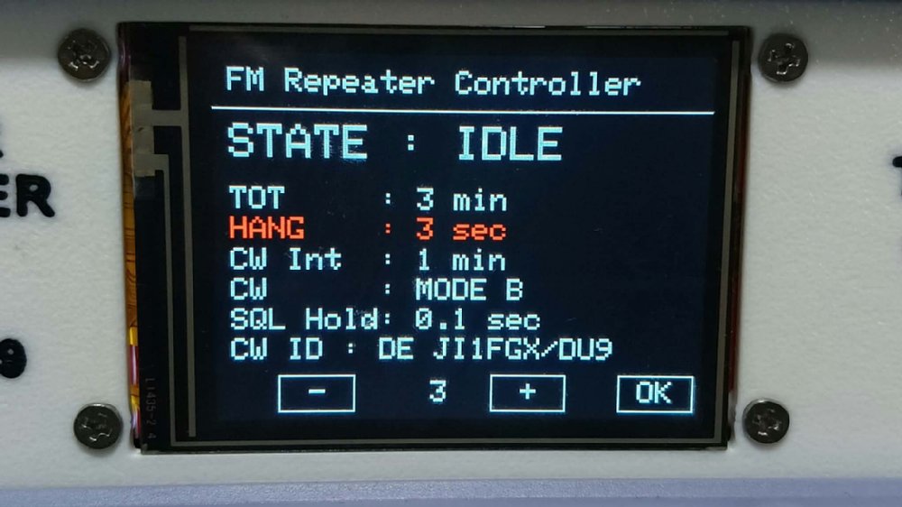 |
||||||||||||||||||||||||||||||||||||||||||||||||||||||||||||||||||||||||||||||||||||||||||||||||||||||
| CW ID Interval
Select OFF, 1 minute (for testing), or 5, 10, 15, 30, or 60 minutes. The firmware suppresses CW at minute 00 to give priority to voice ID. Check the actual transmission timing on your controller when using the 60-minute setting. 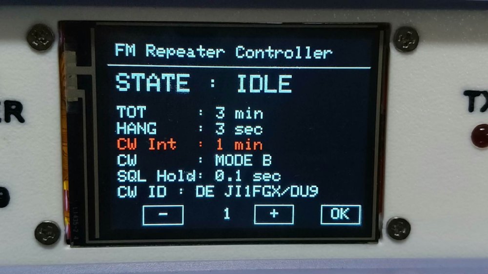 |
||||||||||||||||||||||||||||||||||||||||||||||||||||||||||||||||||||||||||||||||||||||||||||||||||||||
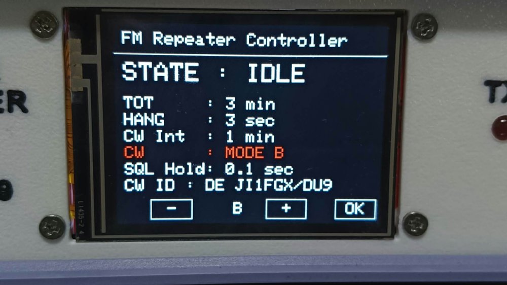
CW MODE
 |
||||||||||||||||||||||||||||||||||||||||||||||||||||||||||||||||||||||||||||||||||||||||||||||||||||||
| Receive Signal Qualification Time (SQL HOLD)
The receive input must remain active for this period before transmission starts. This helps prevent brief noise bursts from triggering unwanted transmissions. On the touchscreen, this can be set from 0 to 5.0 seconds in 0.1-second steps. In the PC settings editor, SQL_STABLE uses units of 100 ms: for example, 3 means 0.3 seconds and 50 means 5.0 seconds. 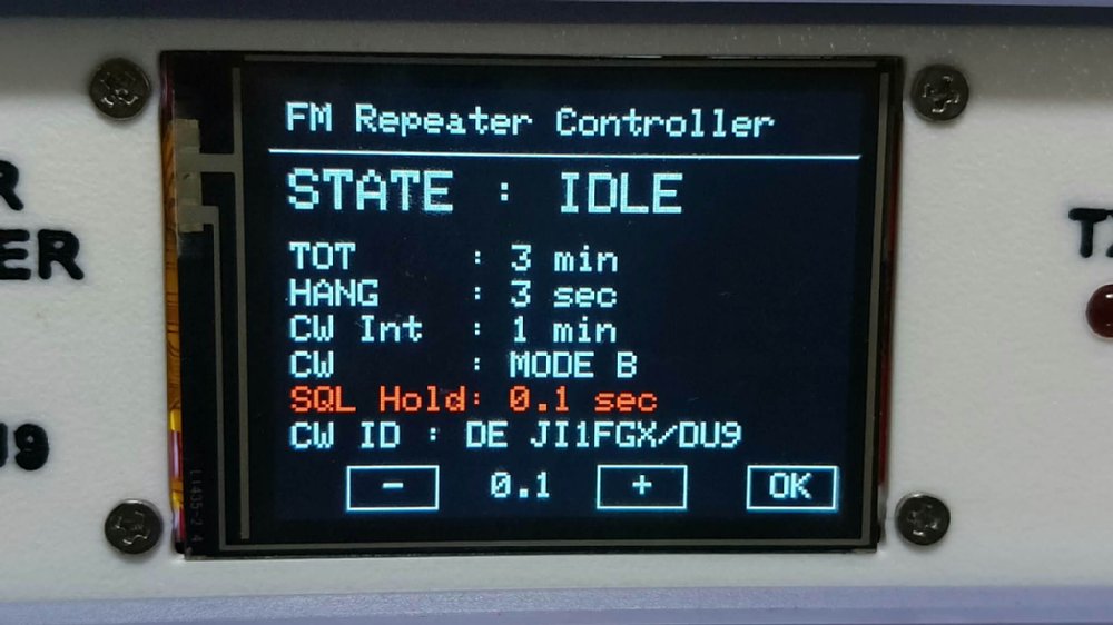 |
||||||||||||||||||||||||||||||||||||||||||||||||||||||||||||||||||||||||||||||||||||||||||||||||||||||
| Editing the CW ID MessageUse the left and right arrows to select a position, and [-] and [+] to change the character. [INS] inserts a space and [DEL] deletes a character. Tap [OK] to save or [C] to cancel. Enter up to 19 characters using uppercase letters, digits, spaces, and /. 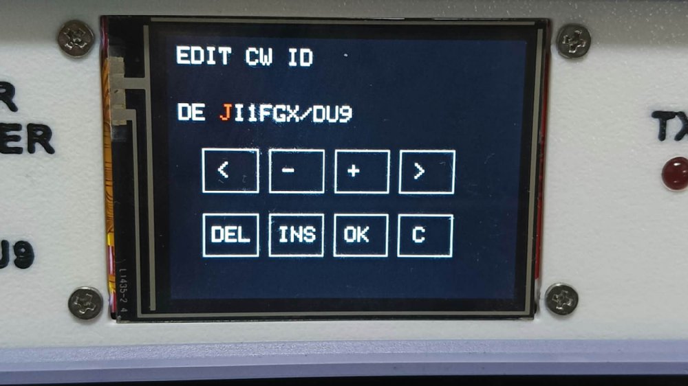 |
||||||||||||||||||||||||||||||||||||||||||||||||||||||||||||||||||||||||||||||||||||||||||||||||||||||
| Repeater Controller PC Settings
Use the Windows settings editor Repeater_Controller_Settings.exe to read and change the settings of a controller connected via USB. The touchscreen provides access to the main settings. The PC settings editor lets you edit the detailed settings below and save them to the controller EEPROM. After connecting via USB, select the COM Port and click [Load] to read the current settings. After editing, click [Save] (the middle button). Close other programs using the same COM port, including the Arduino IDE Serial Monitor. 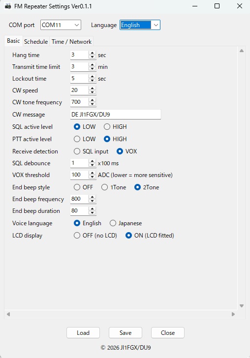 PC Settings ReferenceThe values in the screenshot are examples, not defaults or recommended values. Check the time units carefully: minutes, seconds, or 100 ms. Basic Settings
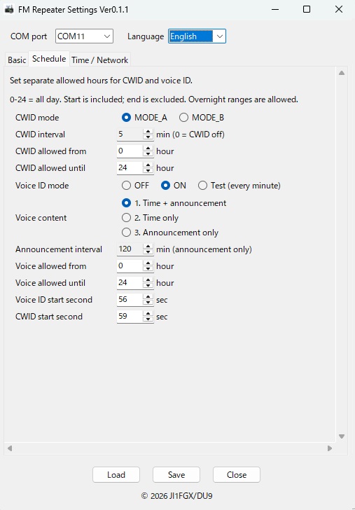 Schedule
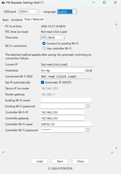 Time / Network
Control Buttons
Start-second settings use the RTC (DS3231) clock. Check the controller clock before using voice ID or scheduled CW. |
||||||||||||||||||||||||||||||||||||||||||||||||||||||||||||||||||||||||||||||||||||||||||||||||||||||
| Browser Configuration over Wi-FiTo connect to an existing Wi-Fi network (STA), enter its network name in Existing Wi-Fi name and its password in Existing Wi-Fi password. Connect your PC or smartphone to the same network to configure the controller in a browser. In the browser address bar, enter an address such as http://fm-rep.local/ or http://192.168.1.66/.Replace the example host name with Hostname, or use the actual address shown in Current IP. If host-name access is unavailable, use the IP address. To connect directly, select Use controller Wi-Fi under Wi-Fi connection and save. The controller does not switch automatically on connection failure. In the Wi-Fi settings on your PC or smartphone, select the controller network name (Controller Wi-Fi name) and enter its password (Controller Wi-Fi password). Then open the controller IP address (Controller Wi-Fi IP) in a browser to configure it. After changing Wi-Fi settings, reconnect using the updated network or IP address. 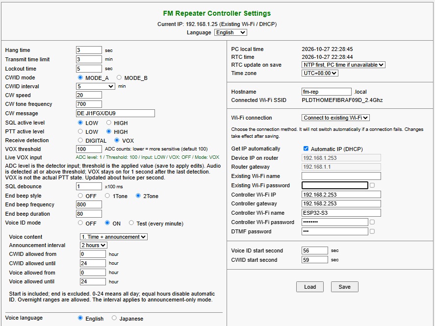 |
||||||||||||||||||||||||||||||||||||||||||||||||||||||||||||||||||||||||||||||||||||||||||||||||||||||
| October 1, 2026 October 4, 2026 | ||||||||||||||||||||||||||||||||||||||||||||||||||||||||||||||||||||||||||||||||||||||||||||||||||||||