| English | Japanese |
Yesterdays access |
|
| Page Top | [Lily Diary.】 A diary of life in Mindanao. |
| 26/09/22 | Kenpro Rotator Interface |
| 26/09/18 | SatBox KiCad PCB and firmware |
| 26/09/14 | designed a circuit board for SatBox |
| 26/09/12 | Solar Power System Plan |
| 26/09/09 | Satellite SatBox Part 4 |
| 26/09/04 | My grandson Zion |
| 26/08/29 | Ham Fair 2026 to be held |
| 26/08/25 | QSO with RI1FJL from Franz Josef Land |
| 26/08/23 | Satellite QSO via RS-44 |
| 26/08/22 | Currently, Satellite VUCC46 |
| 26/08/16 | Satellite SatBox Development in Progress - Part 3 |
| 26/08/05 | IC-820H Receiver Sensitivity Test |
| 26/08/02 | Satellite SatBox Development in Progress - Part 2 |
| 26/07/16 | Delivery of the 3D printed panels |
| 26/07/09 | Development of SatBox for satellites |
| 26/07/05 | Weather Monitor Indoor Unit |
| 26/06/30 | Creating data for 3D printers using FreeCAD |
| 26/06/16 | Installing an AS5600 magnetic encoder on a KR-500. |
| 26/06/05 | Grandson Zion's CQ |
| 26/06/04 | Replacing the potentiometer on the KR-500 elevation rotator |
| 26/06/03 | Making a Repeater Controller Pert4 |
| 26/06/01 | Weather Monitor software |
| 26/05/31 | Weather Monitor |
| 26/05/21 | JTDX Auto Run BUGFIX |
| 26/05/17 | Repair of satellite antenna system |
| 26/05/13 | Repair of Alinco DR130 |
| 26/05/07 | Making a Repeater Controller Pert3 |
| 26/05/03 | Indonesian satellite friend YC8RPK |
| 26/04/26 | DXCC200 achieved |
| 26/04/23 | Communication via ISS voice repeater |
| 26/04/20 | WSJT-X Auto Run Ver0.1.5 |
| 26/04/19 | Got an Alinco DR-130 |
| 26/04/15 | Clublog Charts |
| 26/04/10 | Regarding POC transceivers |
| 26/04/08 | Using KENWOOD AT-300 with YAESU radio |
| 26/03/17 | How to establish a radio club in the Philippines |
| 26/03/10 | KENWOOD AT-300 with YAESU radio |
| 26/02/27 | Philippine NTC Amateur Radio License Examination Question Bank |
| 26/02/20 | Package received from JK1SNS |
| 26/02/18 | Temporary License Renewal |
| 26/02/14 | Satellite Tracking Software SatTrack |
| 26/02/05 | Making a Repeater Controller Pert2 |
| 26/02/02 | CQ on satellite IO-86 |
| 26/01/27 | Shack & Repeater Controller |
| 26/01/16 | Making a Repeater Controller |
| 26/01/16 | Making aRotator Interface PCB |
| 26/01/10 | Satellite antenna installation |
| 26/01/08 | WSJT-X Remote Operation |
| 26/01/07 | JTDX Remote Operation |
| 26/01/04 | log_reciver_Ver2.6.6 |
| 26/01/04 | Tailscale VPN software for JTDX_Remote |
| Online Multiple Choice Reviewers to the Phil Amateur Radio Examination by 4F3EW A joint project by JI1FGX/DU9 and DV9JRD |
| Solar Power System Plan STEP 1 / STEP 2 / STEP 3 (2026/09/12) | ||||||||||||||||||||||||||||||||||||||||||||||
|---|---|---|---|---|---|---|---|---|---|---|---|---|---|---|---|---|---|---|---|---|---|---|---|---|---|---|---|---|---|---|---|---|---|---|---|---|---|---|---|---|---|---|---|---|---|---|
| In Mindanao, Philippines, power outages occur several times a month.
Short outages last around 10 minutes, while scheduled outages for transmission
and distribution line maintenance can last from 6 to 13 hours. Electricity prices in the local Mindanao market also rose to approximately ₱20(US$0.32) per kilowatt-hour (kWh) in August due to tight power supply. Our monthly electricity bill used to be around ₱7,500 (about US$135) to ₱8,500 (about US$153), but it looks like it may increase even further. These circumstances prompted me to take another look at solar power and research the available options. |
||||||||||||||||||||||||||||||||||||||||||||||
ObjectiveThe initial objective is to operate one 1.5 HP inverter air conditioner, five electric fans, eight LED lights, and one amateur radio transceiver from solar power and battery storage.STEP 2 expands the system to two 1.5 HP inverter air conditioners, five electric fans, eight LED lights, one refrigerator, and two amateur radio transceivers. The two radios will not be used for simultaneous transmission. STEP 3 expands further to include the well pump, microwave oven, LCD TV, and up to four laptop computers, covering the major household electrical loads. STEP 1 and STEP 2 use the 6.5 kW / 48 V hybrid inverter. For STEP 3, a 10 kW / 48 V-class hybrid inverter is planned for greater load and motor-starting margin. |
||||||||||||||||||||||||||||||||||||||||||||||
Actual Household Loads (from nameplates)
|
||||||||||||||||||||||||||||||||||||||||||||||
Recommended InverterConfirmed Specifications from the Actual Unit's Nameplate (Added September 15, 2026)The supplied photograph of the actual unit's nameplate is the primary source for the following design values for the ECG-HVM6.5K-48V (6.5 kW / 48 V) used in STEP 1 and STEP 2.
The earlier answers stating “maximum Voc 120 V” and “MPPT 120–500 V” were incorrect. Future calculations for this model will use MPPT 60–450 V and maximum Voc 500 V. Implications for STEP 1–3These specifications allow consideration of series-connected panels operating at approximately 200–400 V for a high-voltage MPPT arrangement. The MPPT operating range and maximum open-circuit voltage are separate constraints. Select the series panel count with margin so that string Voc never exceeds 500 V, accounting for panel Voc at the lowest design temperature, its temperature coefficient and manufacturing tolerances. Operating Vmp must also remain within 60–450 V across the expected temperature range. Using the panel values listed on this page, STEP 1 (4S) and STEP 2 (4S2P) have a Vmp of approximately 171.8 V, within the MPPT range. However, STEP 2 has a combined Imp of approximately 25.64 A and Isc of approximately 27.48 A; its connection arrangement remains provisional until the manufacturer confirms the permissible PV short-circuit current. The 9,000 W maximum PV input rating alone does not establish compatibility: voltage and current limits must also be met. The 120 A PV charge rating and 120 A AC charge rating must be distinguished from the 27 A PV input rating and 40 A AC bypass rating. Do not add the two charge ratings to assume that 240 A charging is available. Confirm the combined charging limit and the battery/BMS permissible charge current before setting charging parameters. For the STEP 3 10 kW-class inverter, recalculate using the selected model's specifications rather than this unit's nameplate values. STEP 1 / STEP 2: 6.5 kW / 48 V hybrid inverter・230 V pure sine wave output ・MPPT range: 60–450 V DC ・Maximum PV open-circuit voltage (Voc): 500 V DC ・Maximum PV input current: 27 A ・Maximum stated PV input power: 9,000 W, subject to voltage and current limits ・48 V-class LiFePO₄ battery system STEP 3: 10 kW / 48 V-class pure-sine hybrid inverter The larger inverter provides additional margin for well-pump and refrigerator motor starting, microwave use, and two air conditioners. Multiple MPPT inputs are preferable. |
||||||||||||||||||||||||||||||||||||||||||||||
STEP 1: One Air Conditioner + Five Fans + Lighting + One Radio
PV array: 4 × genuine 550 W-class panels = approximately 2.2 kWp
Including five fans at approximately 225–300 W total, an air-conditioner average of about 800 W, 80 W of lighting and 250–350 W for radio transmission gives roughly 1.2–1.3 kW during normal operation and around 1.4–1.5 kW while transmitting.
Battery: 1 × 51.2 V 100 Ah LiFePO₄ = approximately 5.12 kWh Inverter: 1 × 6.5 kW / 48 V hybrid inverter Loads: one 1.5 HP inverter air conditioner, five electric fans, eight LED lights, and one amateur radio transceiver |
||||||||||||||||||||||||||||||||||||||||||||||
STEP 2: Two Air Conditioners + Five Fans + Lighting + Refrigerator + Two Radios
PV array: 8 × genuine 550 W-class panels = approximately 4.4 kWp
Including the five fans, the estimated simultaneous load is approximately 2.4–3.6 kW.
Battery storage: 2 × 51.2 V 100 Ah LiFePO₄ in parallel = 51.2 V 200 Ah / approximately 10.24 kWh Inverter: continue using the same 6.5 kW / 48 V unit from STEP 1 Loads: two 1.5 HP inverter air conditioners, five electric fans, eight LED lights, refrigerator, and two amateur radio transceivers Radio operation: no simultaneous transmission |
||||||||||||||||||||||||||||||||||||||||||||||
STEP 3: Cover All Major Household AppliancesUsing the confirmed nameplate values and planning both air conditioners at the upper end of 1.3 kW each, a demanding case with the well pump, refrigerator, microwave, TV, five electric fans, four laptops, eight LED lights and both air conditioners operating at the same time is approximately 6.0 kW of continuous load. Motor-starting surges from the pump and refrigerator leave limited margin on a 6.5 kW inverter.
Recommended inverter: 10 kW / 48 V-class pure-sine hybrid inverter, preferably with multiple MPPT inputs
For STEP 2 and STEP 3, confirm that the manufacturer explicitly permits parallel operation of the 51.2 V 100 Ah batteries, including the maximum parallel count, BMS continuous-discharge rating, and communication method. A 10 kW inverter can require roughly 200 A on the 48/51.2 V DC side near full output, so BMS rating, busbars, fuses, breakers and cable sizing become critical.
PV array: 12 × genuine 550 W-class panels = approximately 6.6 kWp Battery: 3 × 51.2 V 100 Ah LiFePO₄ in parallel = 51.2 V 300 Ah / approximately 15.36 kWh Design loads: well pump, refrigerator, microwave, TV, two air conditioners, five electric fans, up to four laptops, and eight LED lights | ||||||||||||||||||||||||||||||||||||||||||||||
Preliminary Equipment Cost Estimate
If STEP 1 reduces the current PHP 8,500 monthly electricity bill by approximately 30–40%, the monthly savings would be about PHP 2,550–3,400 and the equipment-only simple payback period would be approximately 28–40 months. If STEP 2 reduces it by approximately 70–80%, the estimated simple payback period is approximately 25–31 months. Actual payback depends on solar irradiation, air-conditioner operating hours, daytime versus nighttime use, battery losses, weather and electricity rates. |
||||||||||||||||||||||||||||||||||||||||||||||
STEP 3 versus a GeneratorThe demanding STEP 3 simultaneous load is approximately 6.0 kW. Allowing for starting the well-pump motor and refrigerator compressor, the more appropriate comparison is an 8–10 kVA single-phase 220/230 V generator.A generator can have a much lower initial cost, but it continuously consumes fuel whenever operating and adds recurring fuel cost, noise, exhaust and maintenance. STEP 3 solar has the higher initial cost but is intended to reduce normal electricity bills while also providing outage backup. Current 8–10 kVA generator prices should be checked at purchase time because they vary widely by fuel type, brand, and open-frame versus silent construction. For amateur-radio use, RFI from either a generator or solar inverter should also be tested in practice. |
||||||||||||||||||||||||||||||||||||||||||||||
Example PV String ArrangementUsing the LONGi Hi-MO 6 550 W panel as a reference (Vmp 42.95 V, Imp 12.82 A, Voc 51.40 V), four panels in series for STEP 1 give approximately 171.8 V at Vmp, 205.6 V Voc and 2.2 kWp.For STEP 2, a 4S2P arrangement gives approximately 171.8 V, 25.64 A operating current and 4.4 kWp. The two parallel strings have a combined Isc of approximately 27.48 A, so it is necessary to confirm whether the inverter's stated 27 A maximum PV input current is an operating-current limit only or also a hard short-circuit-current limit. For STEP 3, the 12-panel 6.6 kWp array must be redesigned around the actual MPPT input count and current ratings of the selected 10 kW inverter. |
||||||||||||||||||||||||||||||||||||||||||||||
Main Concern: HF Radio-Frequency Interference (RFI)For an amateur radio station, the main concern is switching noise from the MPPT controller or inverter coupling onto the PV wiring and then radiating from long DC conductors or nearby solar-array structures into the HF bands.・Install a proper PV DC isolator/breaker ・Install a DC breaker on the battery side ・Ensure the inverter can be completely powered down ・Keep positive and negative PV conductors close together and avoid unnecessary loops ・Keep PV wiring as far as practical from HF antennas and coaxial feed lines ・Use suitable ferrite common-mode suppression if testing shows it is required ・Measure HF noise at STEP 1 before expanding to STEP 2 / STEP 3 RFI performance cannot be guaranteed from a specification sheet alone. Compare the HF noise floor with PV connected/disconnected and with the inverter on/off. |
||||||||||||||||||||||||||||||||||||||||||||||
GlossaryPV / Photovoltaic: Solar generation.kWp: Total rated peak power of a PV array. MPPT: Maximum Power Point Tracking. Vmp: Voltage at maximum power. Imp: Current at maximum power. Voc: Open-circuit voltage. Isc: Short-circuit current. 4S2P / 2P / 3P: S means series; P means parallel. LiFePO₄: Lithium iron phosphate battery chemistry. BMS: Battery Management System. Ah: Ampere-hour, a battery-capacity unit. kWh: Unit of energy or battery storage. Pure Sine Wave: AC waveform similar to utility power. Hybrid Inverter: An inverter that manages PV, battery, utility power and AC loads. DC Isolator: A switch for safely disconnecting PV DC from the inverter. RFI: Radio Frequency Interference. Surge / Starting Current: Temporary high current required when motors start. kVA: Apparent-power unit commonly used for generator ratings. |
||||||||||||||||||||||||||||||||||||||||||||||
Important NoteThe power figures, prices and panel electrical values on this page are preliminary planning estimates. The STEP 3 values of a 10 kW inverter, 6.6 kWp PV array and 15.36 kWh battery bank are also planning figures. Before purchase and installation, confirm the actual 10 kW inverter MPPT voltage/current/input count, panel Voc / Vmp / Imp / Isc, battery BMS limits, both air-conditioner nameplates, cable sizing, protection devices, grounding and local electrical requirements. |
||||||||||||||||||||||||||||||||||||||||||||||
Inverter Features and Operation in STEP 1
In particular, features 1 and 2 are very well suited to the operation we had in mind for STEP 1. Without purchasing an expensive 51.2 V LiFePO₄ battery at the outset, we can start with the following arrangement:
PV → Inverter → Household loads
+ Shortfall ← Utility power (Grid) A battery can be added later. 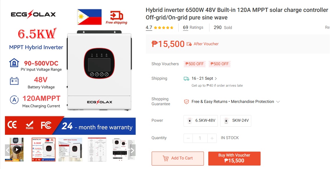 |
||||||||||||||||||||||||||||||||||||||||||||||
 |
||||||||||||||||||||||||||||||||||||||||||||||
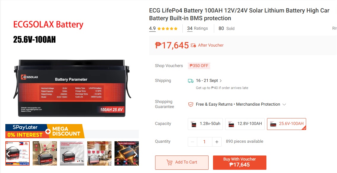
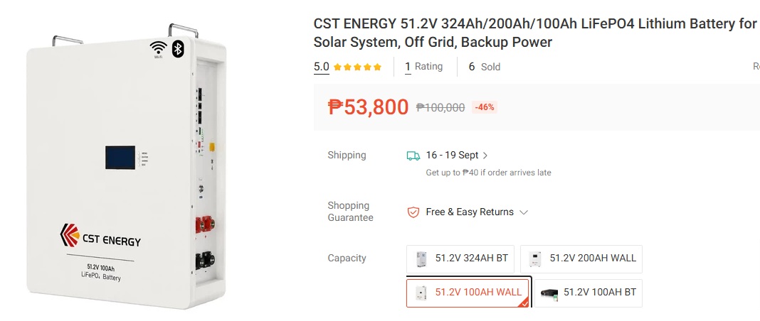 Difference between 25.6 V and 51.2 V batteries When 25.6 V 100 Ah LiFePO₄ batteries are used with a 48 V-class inverter, two batteries must be connected in series to obtain 51.2 V 100 Ah, or approximately 5.12 kWh. A 51.2 V 100 Ah LiFePO₄ battery is already designed for a 48 V-class system, so STEP 1 requires only one battery to provide approximately 5.12 kWh. For this reason, the revised plan no longer uses series-connected 25.6 V batteries. It uses one 51.2 V 100 Ah battery in STEP 1, two in parallel in STEP 2, and three in parallel in STEP 3. This simplifies the wiring and avoids the additional complications of putting separate battery BMS units in series. |
||||||||||||||||||||||||||||||||||||||||||||||
|
Good candidates to consider are the JinkoSolar Tiger Pro 550W-class panels and the LONGi Hi-MO 5/6 550W-class panels. JinkoSolar’s official specifications include Tiger Pro 72HC models in the 530–550W range, while the LONGi Hi-MO 6 550W model has dimensions of 2278 × 1134 mm, with Vmp 42.95V, Imp 12.82A, and Voc 51.40V. Using this LONGi 550W panel as a reference, it is also a very good match for the solar system currently being considered. STEP 1: 4 panels in series → 2.2kWp, Vmp approximately 172V STEP 2: 4S2P → 8 panels, 4.4kWp, Imp approximately 25.6A This configuration is therefore a good electrical match for the inverter
under consideration, It is also worth noting that a genuine 550W-class solar panel is quite
large, 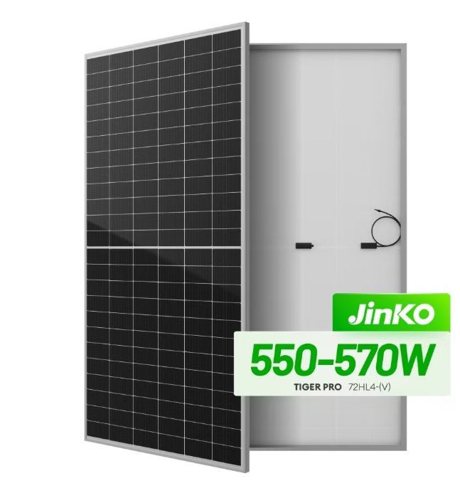 |
||||||||||||||||||||||||||||||||||||||||||||||
| September 9, 2026 September 14, 2026 | ||||||||||||||||||||||||||||||||||||||||||||||